
Having said "freelance" the latest project does not come under that banner, this job is going to be as close to a prototype as i can make it.
I have always liked the little 0-4-0 saddle/well tank engines of the Darjeeling and Himalayan railway, there's something about the "toy train" that has character and charm.
Anyway I digress, I have recently made a start on scratch building a DHR class B loco, using drawings given to me by a friend.
First job is the chassis and in particular the connecting rods as these set the datum for the frame axle holes or horn block guides.
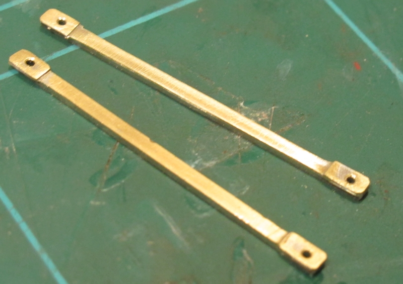
(I always keep these bits after I have used the components on a fret just for this type of job)
The strip is laminated to give strength and a 3rd lamination at each end for the bearing bosses.
Clamped together for drilling ensures the hole centres are the same for both rods.

It is surprisingly strong and rigid and solders like a dream with less heat required than using brass or nickel silver.
to cut the frames I printed out the frames drawing to 1/43 scale, stuck it to the PCB and cut out with a fine toothed fret saw and files. By clamping the two together and cutting both at the same time. The con rods were then used to mark and drill for the axle positions.
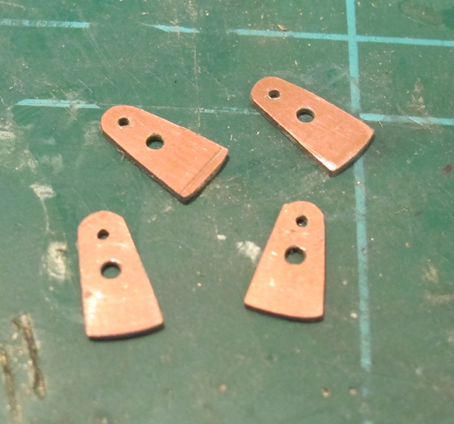
again cut from the same material as the frames.
I used a Romford crank as a starting point and drilling template for the hole centres. The cranks were then bolted together through the axle hole using a 10 BA screw and nut whilst they were filed to shape thus ensuring they were all the same and the correct shape of the prototype.
14 BA pins and nuts are used as crank pins, the screws being soldered in from the rear of each crank.
When i write the next entry to this blog regarding this project I will have assembled the frames and hopefully have a free running rolling chassis.
More soon and Cheers!
Frank
Using PCB board for frames is an interesting idea, I shall watch with interest. I believe that some 2mmFS modellers use .5mm double sided PCB. Coupling rods look neat, I always keep scrap etch as well.
ReplyDelete